MK0
- RIGHT ARM
- FULL SUIT
- MEDIA
- FLAMETHROWER
- HIDDEN BLADE
- TASER
- DESIGNS
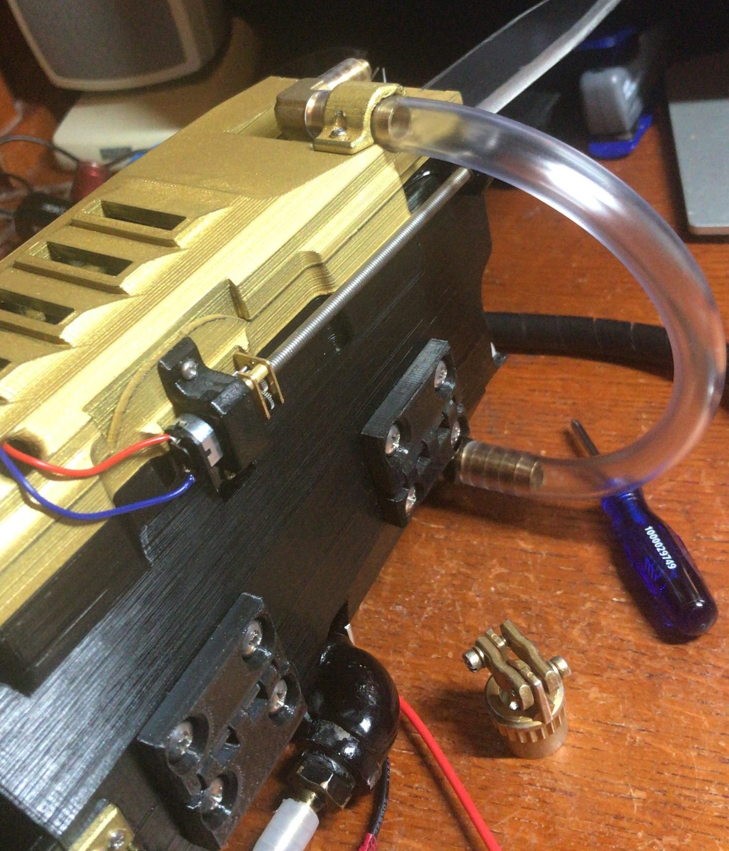
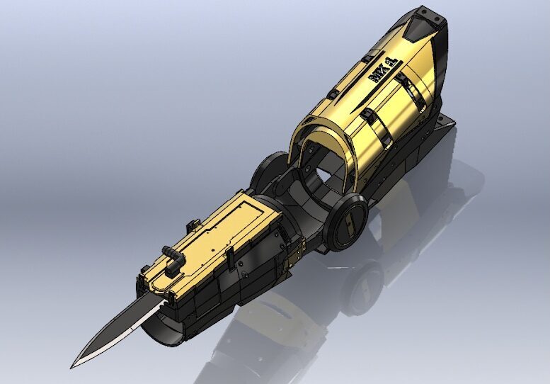
RIGHT ARM FLAMETHROWER
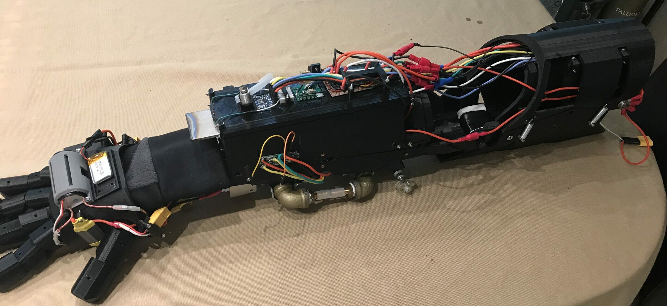
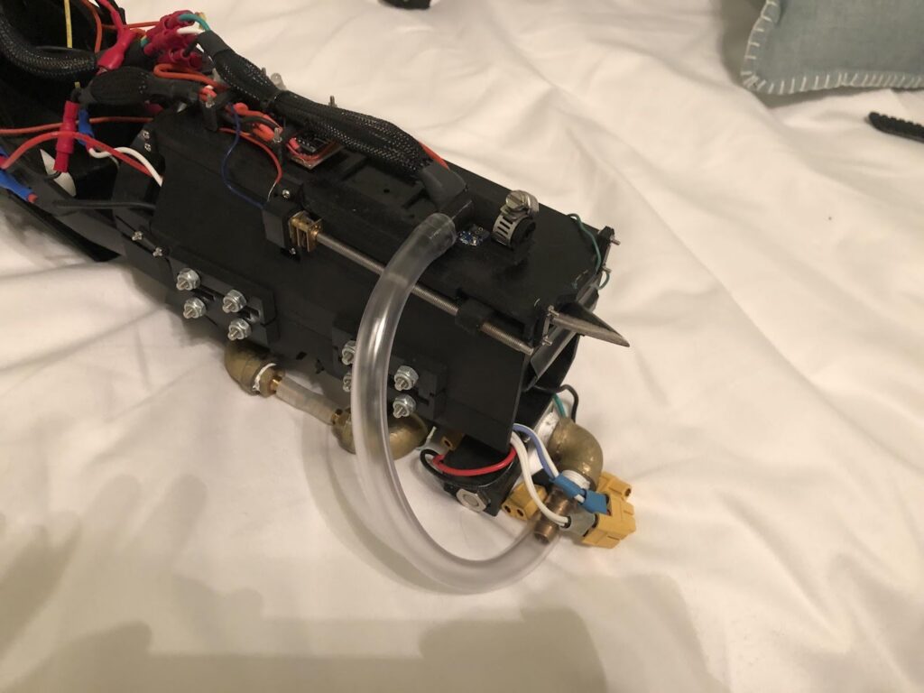
Mechanics

On the top of the forearm, the output nozzle, igniter, and accelerometer were fastened to the frame, and the fuel tanks were mounted on the bottom of the forearm.

With the accelerometer located towards the end of the user’s forearm, better acceleration data could be captured to improve the accuracy of the trigger system.
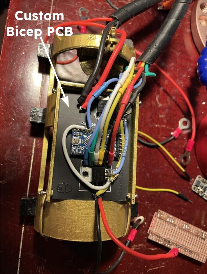
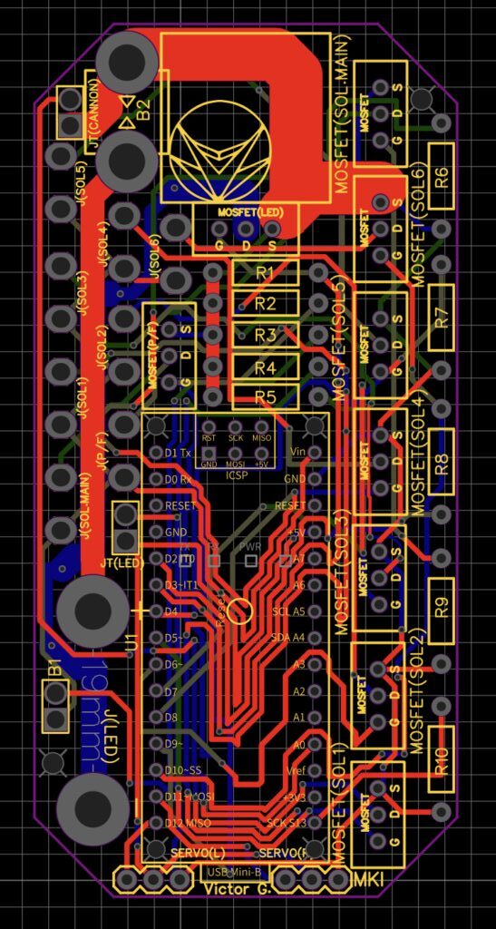
Electronics
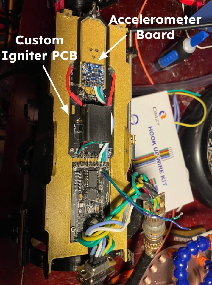
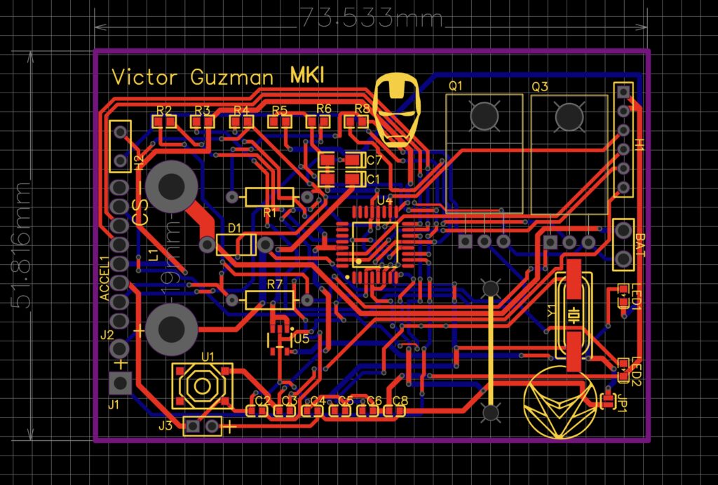
The accelerometer sent data to an Arduino pro mini mounted on the bicep PCB (Right image).
On that same board, two MOSFETs received gate signals from the Arduino to trigger the igniter and solenoid valve. The igniter also had its own PCB surrounding the accelerometer (Left image).
Software and Testing
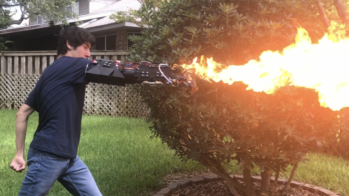
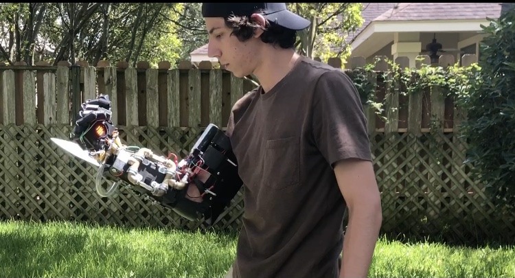
- The Arduino was programmed to take the accelerometer data from the forearm to open the solenoid valve and activate the arc lighter when a “punch-like” acceleration was detected
- The butane gas stored in the tanks at the base of the forearm would be expelled through the arc from the igniter creating the flame
- The punch activation feature was adopted from the first flamethrower iteration
RIGHT ARM HIDDEN BLADE
Mechanics

To lock and unlock the blade retaining mechanism, a lead screw actuated a flat plate which compressed the locking springs on one side of the blade and allowed the opposing springs to become active. To lock and unlock the blade retaining mechanism, a lead screw actuated a flat plate which compressed the locking springs on one side of the blade and allowed the opposing springs to become active
The compressed springs allowed the blade to move towards the direction of the active springs, which allowed the blade to slide past them but prevented the blade from moving in the opposite direction. This feature allowed for a locked blade in its retracted or ejected position
Electronics
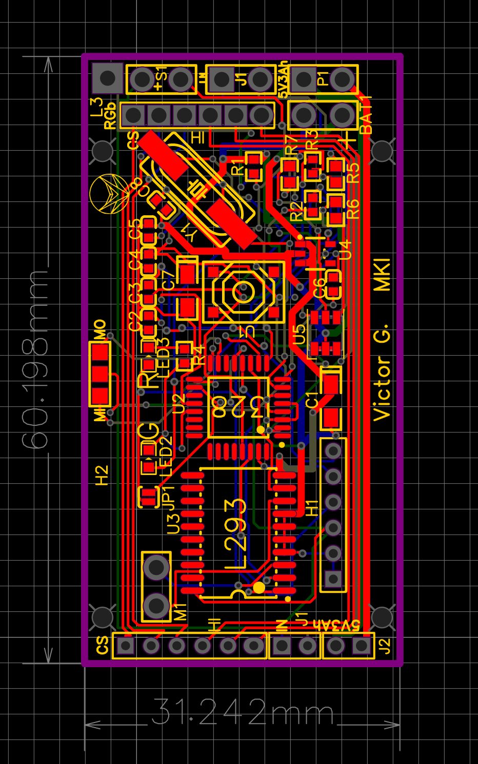
The board above is an Arduino Pro mini with an integrated motor drive to control the lead screw.
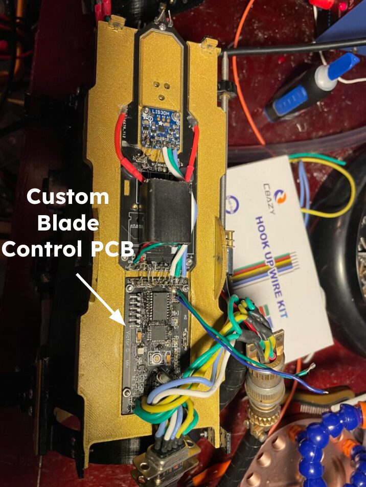
The board also passed the accelerometer signals through it to reduce harnessing space
Software and Testing
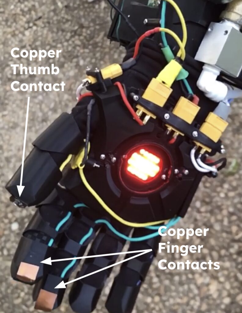
- To control the blade the finger contacts were used as triggers to unlock/lock the blade so it could be retracted/ejected.
- Using a simple Arduino-Button configuration the thumb contact would short across the index finger to contact to arm or disarm the system and then acrtoss the middle finger contact to unlock or lock the blade
- The Arduino would keep a memory of the most previous state and tell the lead screw to move the spring adjusting plate in the appropriate direction.
RIGHT ARM PALM TASER
System Features
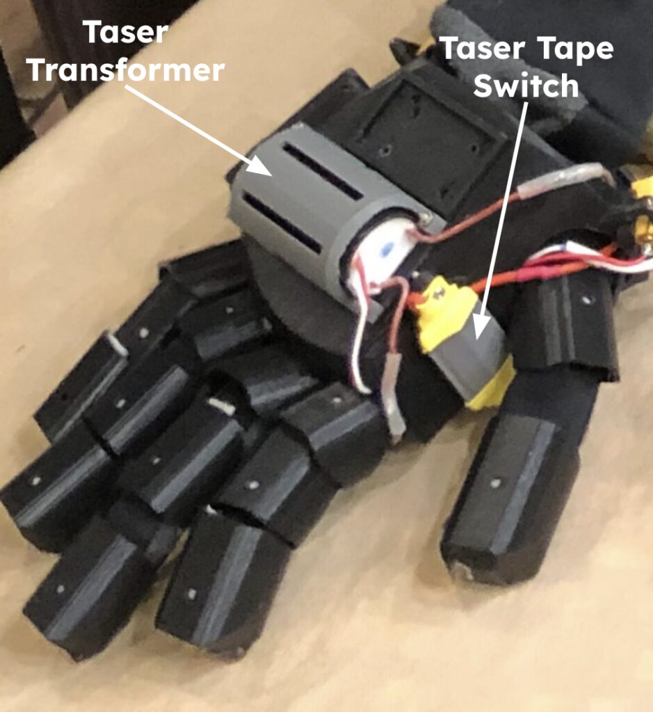
- The palm taser was controlled by a momentary tape switch wired in series with a positive power wire to the taser’s transformer
- The transformer output was then routed to the prongs on the palm
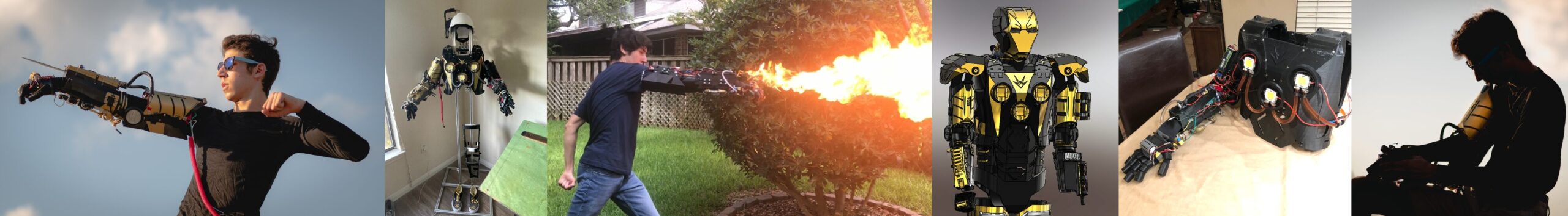
DESIGN EVOLUTION
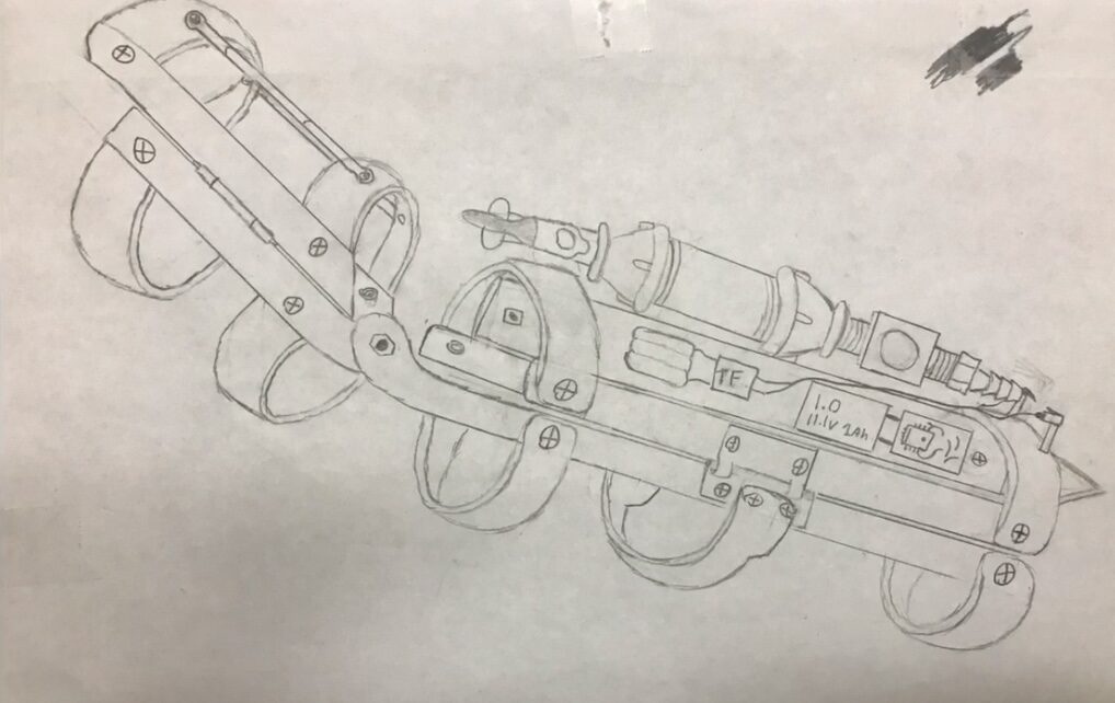
Preliminary Sketch
- Originally planned to be a bare bones frame for mounting the subsystems with no plans for a full suit or even a glove
- The flamethrower and retractable blade were the only subsystems the arm was going to have
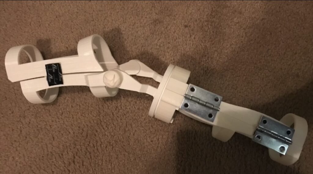
Initial Prototype
- Sticking to the plans for a bare bones frame a 3D printed version was made with PLA
- This prototype was developed after many iterations of trying to align the design with the dimensions of my arm
- At this stage hinges were used to allow the bicep and forearm to ope so I could wear it while velcro was used as a way to secure it when it was being worn
Upgraded Prototype
- A glove model was added with plans for an LED to be in the center
- The bicep and forearm were loosely adjusted to make space for the electronics and parts needed for the subsystems to be added
- The hinges were now 3D printed and fastened to the arm for improved fastening while springs were used on the opposite sides to hold the forearm and bicep pieces together
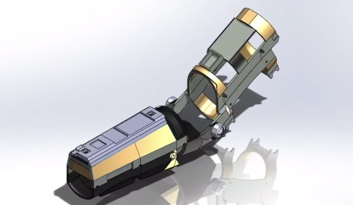
V1
- Stemming from the upgraded prototype the first version was produced reinforcing failure points
- The bottom and top forearms now had full covering to add more mounting points for all the planned components
- A black and gold color scheme was mildly integrated into the design as well
V2
- Version two further reinforced failure points by adding more coverage to the bicep and elbow area
- At this stage the plan for a bare bones frame was discarded and full covering was planned moving forward
- To fasten the forearm and bicep, linear brackets were now used that would be screwed in to hold pieces together when worn
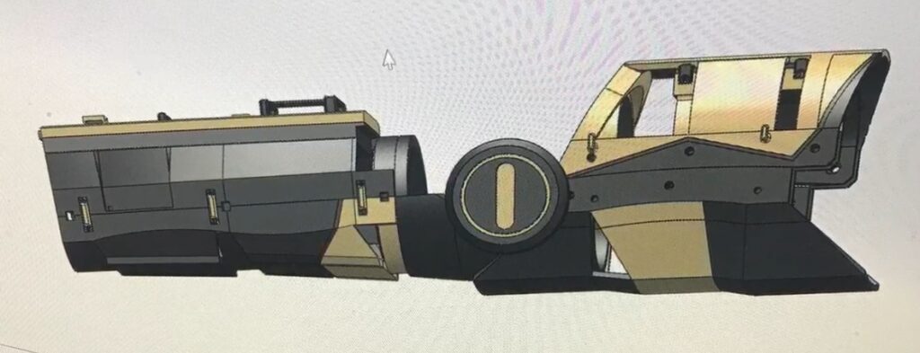
V3
- Aesthetic changes were made and the black and gold scheme was applied to the whole arm
- The blade and flamethrower systems were close to finalization

V4
- Version four was the first attempt at testing the various subsystems with a rough layout of the electronic systems included
- The glove was also modified to include a prototype of the hand taser
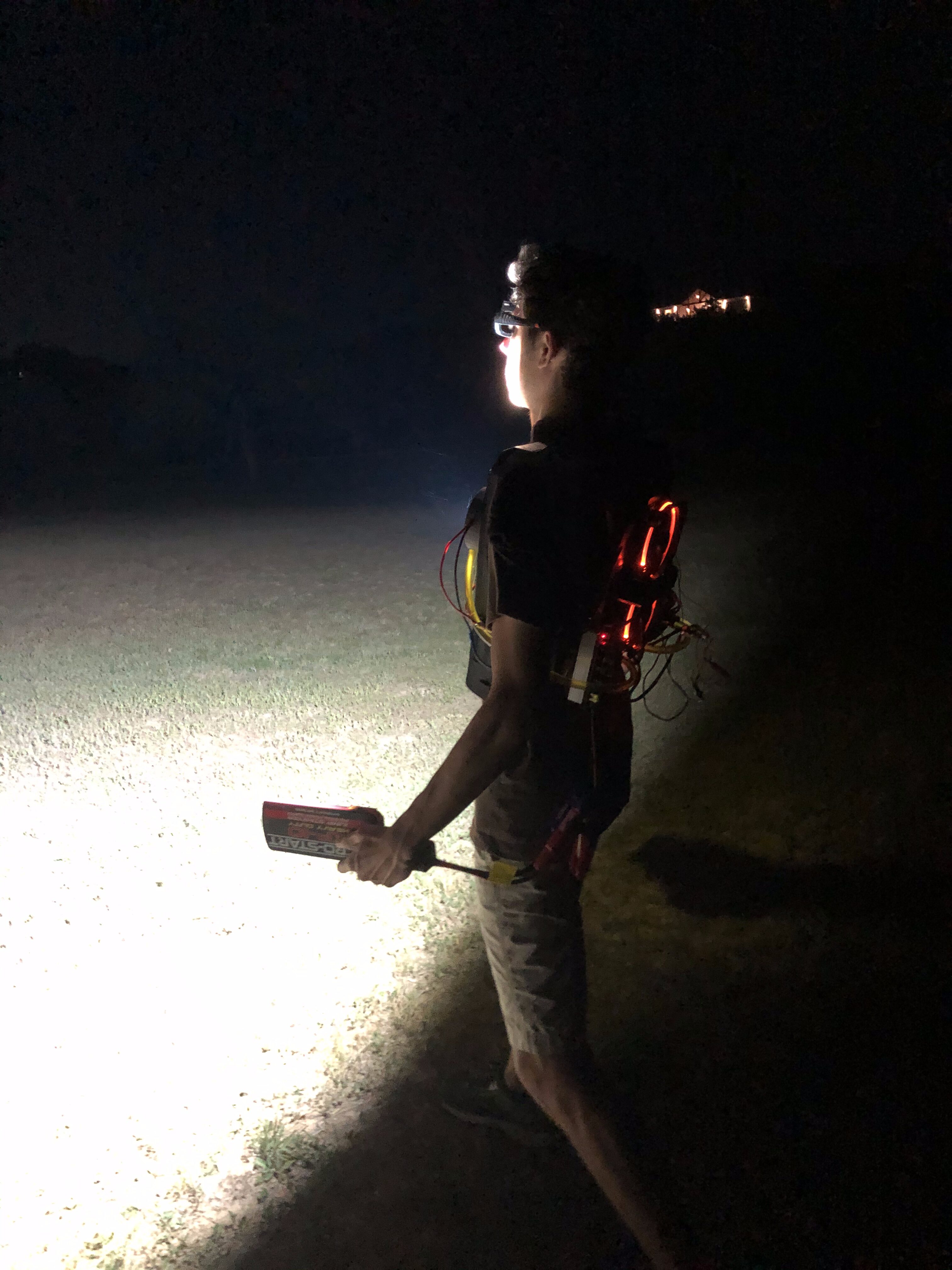
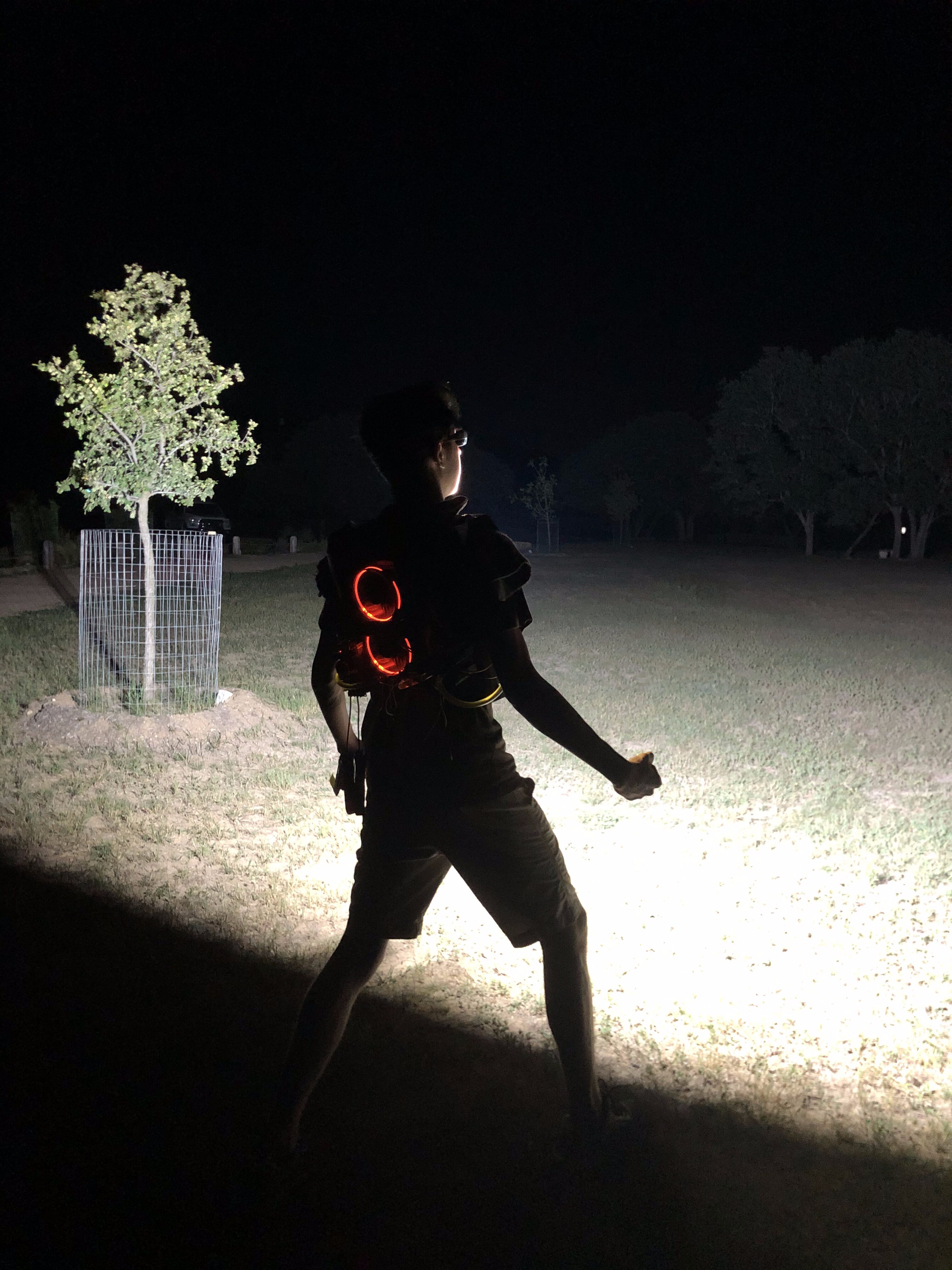
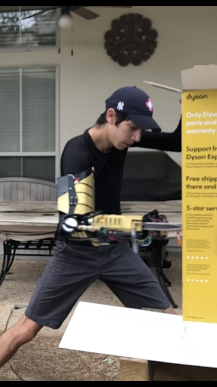
- Both the flamethrower and blade were operational and various tests with V4 are shown throughout the project page

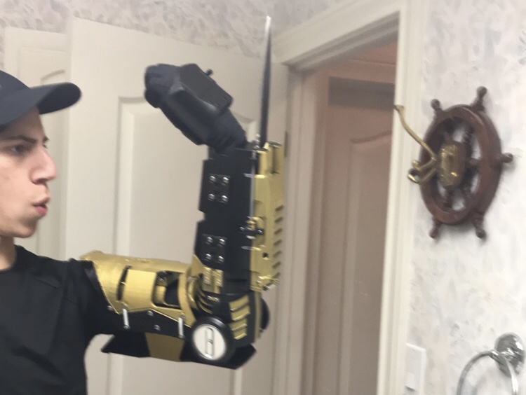
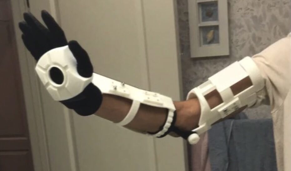
Finalized Right Arm MKI
- Once V4 was validated the finalized version was produced with a full paint job
- The flamethrower and blade controls were move to custom electronics instead of protoboards
- Wire management was also improved to allow for better wearability
- 3D printed hinges were still in use but now small metal latches were used to hold the forearm and bicep pieces together during operation
- 100W LEDS
- DESIGNS
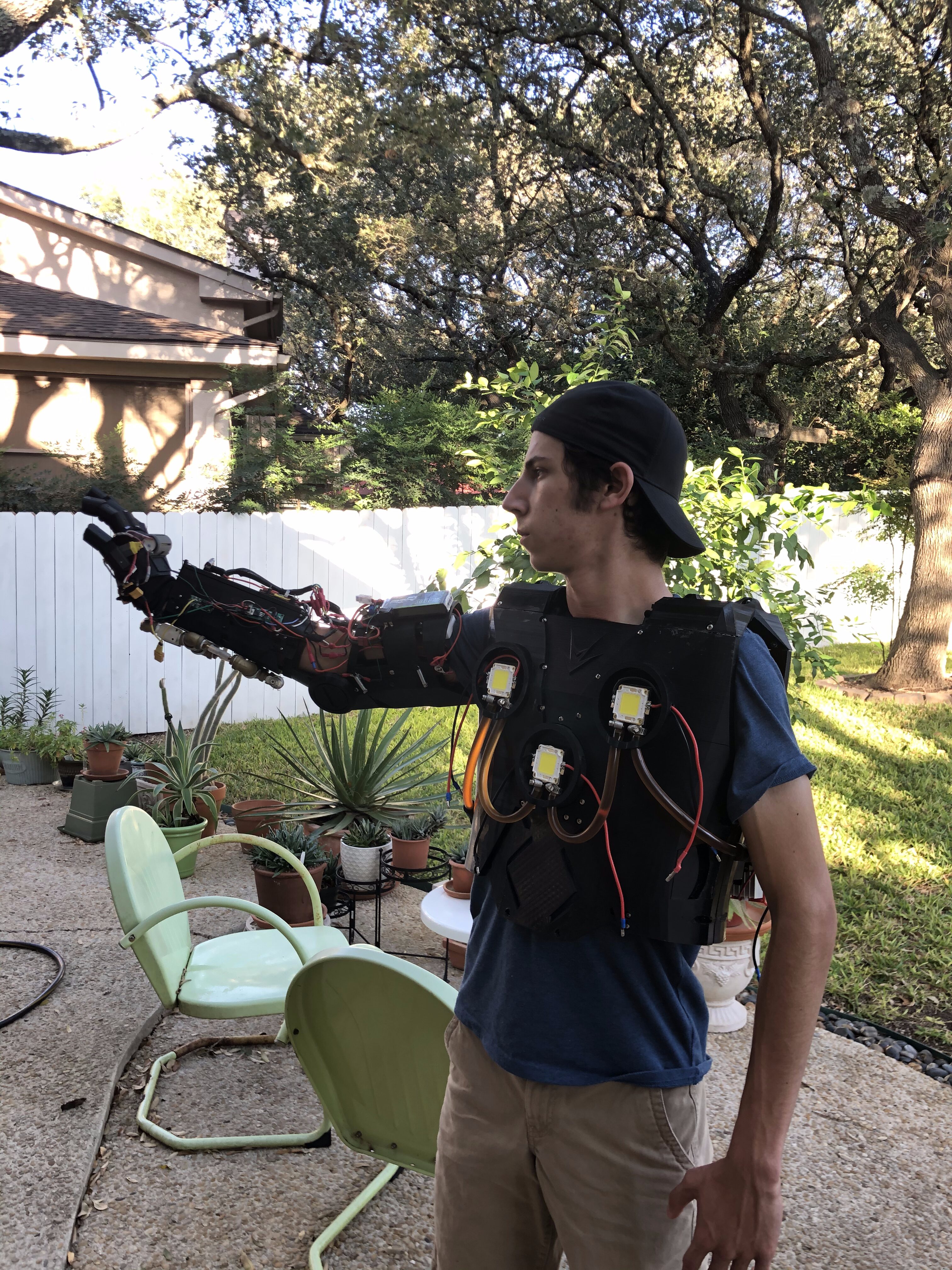
CHEST PLATE LEDS
System Features

DESIGN EVOLUTION
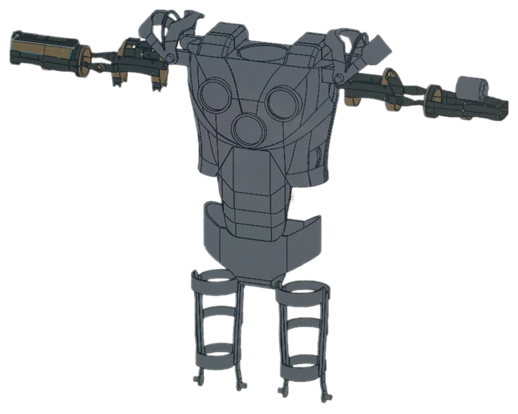
- The design was originally intended to only include the necessary frame components for mounting all the various subsystems leaving most of the body exposed.
- This would allow for less material to be used during production and reduce design complexity. However, this ultimately led to difficulty dawning as the PLA 3D printed parts were much weaker due to very thin designs.
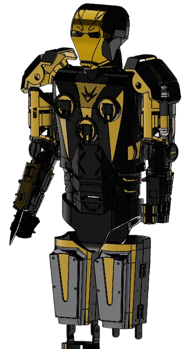
- Note that the left and right arms appear different since the original intention was to have two arms with different capabilities.
- Further down the design timeline, a more complete version of the suit was created adding more coverage to the previously exposed parts.
- An Iron Man mask was designed as a visual scaling aid. The legs were also updated to include covers for the batteries that were intended to power the suit.
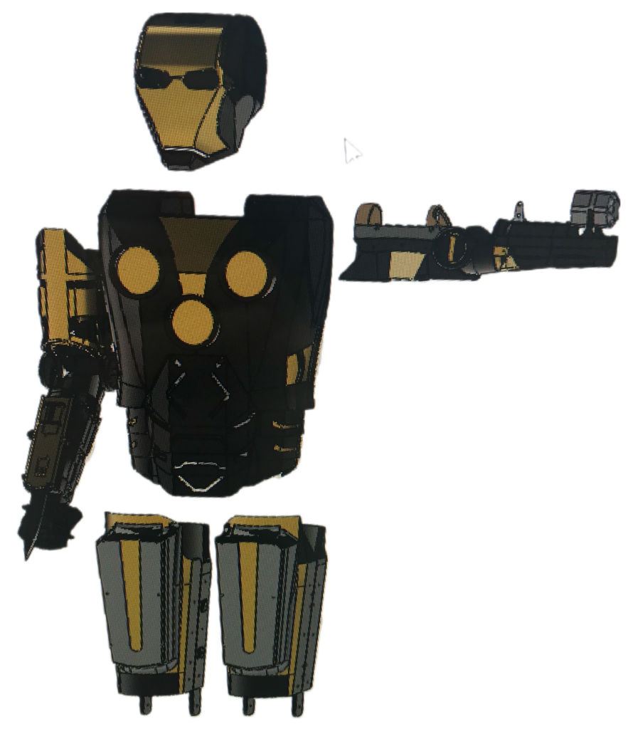
- Following a similar design goal the next changes to the suit involved completing the first functioning right arm and furthering the left arm assembly.
- Chest piece functionality was also implemented, with slots for the 100W LEDs included to attach the system. More coverage was added, and some subtle aesthetic changes were made to the mask, chest, and appendages.
- The midsection pieces were also further developed with plans to produce them out of a flexible filament to remove restrictions on degrees of freedom in that area. There were also pockets added to the midsection pieces to improve material compliance in that area.
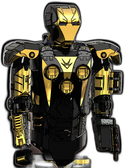
- Version 0.9 highlights the most complete suit designs produced. With upgraded chest piece functionality, a finalized right arm system, a completely redesigned left arm, and added mask functionality.
- Notably, the shoulder pads were also redesigned with movement in mind, connecting them to the arms with flexible interfaces. The legs remained relatively untouched as their full functionality had not been defined at this point.